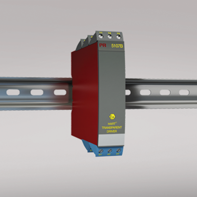
5107B
HART® transparent driver
- 1- or 2-channel version
- 3- / 5-port 3.75 kVAC galvanic isolation
- < 1.3 V voltage drop on input
- 16 V driving voltage on Ex / I.S. output
- Universal supply by AC or DC
Manuals : 
Data sheet :
Application
- Safety barrier for current signals and 2-way HART®communication transmitted to I/P converters mounted in hazardous area.
- Safety barrier for 2-way HART® communication and analog current signals transmitted to hazardous area.
- Signal isolator with low response time on analog current signals transmitted to hazardous area.
Technical characteristics
- PR’s HART® transparent driver primarily processes current signals of 4...20 mA.
- PR5107B is based on microprocessor technology for gain and offset. The analog signal is transmitted at a response time of less than 25 ms.
- Inputs, outputs, and supply are floating and galvanically separated.
Mounting / installation
- Mounted vertically or horizontally on a DIN rail. As the devices can be mounted without distance between neighboring units, up to 84 channels can be mounted per meter.
Environmental Conditions
Specifications range -20°C to +60°C Calibration temperature 20...28°C Relative humidity < 95% RH (non-cond.) Protection degree IP20 Mechanical specifications
Dimensions (HxWxD) 109 x 23.5 x 130 mm Weight approx. 260 g DIN rail type DIN 46277 Wire size 1 x 2.5 mm2 stranded wire Screw terminal torque 0.5 Nm Common specifications
Supply voltage, universal 21.6...253 VAC, 50...60 Hz or 19.2...300 VDC Fuse 400 mA SB / 250 VAC Max. power consumption ≤ 2 W (2 channels) Internal consumption ≤ 2 W (2 channels) Isolation voltage, test / working 3.75 kVAC / 250 VAC Signal / noise ratio Min. 60 dB (0...100 kHz) Accuracy Better than 0.1% of selected range Response time (0...90%, 100...10%) < 25 ms Long-term stability, better than ±0.1% of span / Year Effect of supply voltage change < ±10 μA EMC immunity influence < ±0.5% of span Extended EMC immunity: NAMUR NE 21, A criterion, burst < ±1% of span Input specifications
Current input: Measurement range 4...20 mA Min. measurement range (span), current input 16 mA Input resistance: Supplied unit 10 Ω + PTC, Vdrop < 1.3 V Input resistance: Non-supplied unit Rshunt = ∞, Vdrop < 3.5 V Output specifications
Current output: Signal range 4…20 mA Min. signal range 16 mA Load (max.) 20 mA/800 Ω/16 VDC Load stability, current output ≤0.01% of span / 100 Ω Current limit ≤ 28 mA *of span = of the presently selected range Approvals
EMC EN 61326-1 LVD 2006/95/EC EN 61010-1 PELV/SELV IEC 364-4-41 and EN 60742 ATEX 2004/108/EC DEMKO 01ATEX127484 UL UL 913, UL 508 EAC TR-CU 020/2011 EN 61326-1 EAC Ex TR-CU 012/2011 RU C-DK.GB08.V.00410