7916
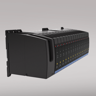
System 9000 backplane
- Provides safe, easy wiring between the backplane and non I.S. automation systems using standard prefabricated I/O cables
- Direct, Redundant and Duplicate signalling - including HART I/O
- Robust, compact high-end design solution for 16 system 9000 units
- Digital output and LEDs indicate backplane system status
Manuals : 
Data sheet :
Application
- The 7916 backplane is a compact and robust solution that enables a safe and easy connection of PR system 9000 IS device signals into standard automation systems.
- Standard automation system cables and connectors are used to link the backplane to the I/O cards.
- The backplane can be used for Direct, Redundant, Duplicate signalling including HART I/O System connectivity (HART MUX).
- The system 9000 devices isolate and convert AI, AO, DI and DO signals coming from, or going to the I.S. classified area, and routes those signals to a system automation I/O card.
- The system 9000 units maintain a SIL2 level of functional safety, even when mounted in the backplane solution.oop.
Technical characteristics
- Robust, compact high-end design that holds 16 system 9000 units.
- Digital output indicates status of the 9000 devices and primary/back-up power supplies.
- Flexible 24 VDC supply voltage and redundant power supply connection solution.
Mounting / installation / programming
- Flexible horizontal/vertical panel or wall mounting in the Safe or Zone 2 / Div 2 areas.
- System 9000 devices easily snap ON and OFF using piano keys, and devices can be hot-swapped.
- Tag number and ID labels are easily mounted and read by using the dedicated piano key spacer.
- Wide temperature operation range: -20...+60°C.
- Backplane selection guide can be found at www.prelectronics.com/backplane
Environmental Conditions
Specifications range -20°C to +60°C Storage temperature -40°C to +85°C Relative humidity < 95% RH (non-cond.) Installation in Pollution degree 2 & measurement / overvoltage cat. II Mechanical specifications
Dimensions (HxWxD) 144 x 443 x 141 mm Wire size 2.5 mm2 / AWG 12 (Supply 1 / 2 and status relay connectors) Common specifications
Supply voltage 20...31.2 VDC (24 DC nom.) Max. power consumption ≤ 60 W Replaceable fuses Fuse F1 & F2: 3.15 A SB, 250 V, type TR5 Isolation voltage, test / working 500 VAC / 50 VAC (Basic isolation between supply 1 & 2 and status relay) Output specifications
Max. voltage, status relay 32 V (Zone 2 / Div. 2 area) 42 V (Safe area) Max. current, status relay 100 mA (Zone 2 / Div. 2 area) 100 mA (Safe area) Approvals
EMC EN 61326-1 UL UL 508 ATEX 2004/108/EC DEKRA 13ATEX0136X IECEx DEK 13.0044X FM 0003049918-C