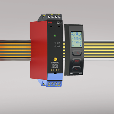
9203B
Solenoid / alarm driver
- Universal Ex driver for solenoids, acoustic alarms and LEDs
- Extended self-diagnostics
- 1 or 2 channels
- Can be supplied separately or installed on power rail, PR 9400
- SIL 2-certified via Full Assessment
Manuals : 
Data sheet :
Advanced features
- Universal I.S. driver for the control of solenoids etc. with various I.S. data by way of three built-in I.S. barriers.
- Two hardware versions make it possible to choose either Low (35 mA) or High (60 mA) current output.
- Configuration and monitoring by way of detachable display front (PR 4501).
- Selection of direct or inverted function for each channel via PR 4501 and the possibility of reducing the output current to the hazardous area to suit the application.
- Optional monitoring of the output current to the hazardous area by way of PR 4501.
- Optional redundant supply via power rail and/or separate supply.
Application
- 9203B can be mounted in the safe area or in zone 2 / div. 2 and transmit signals to zone 0, 1, 2 and zone 20, 21, 22 including M1 mining / Class I/II/III, Div. 1, Gr. A-G.
- The 9203B is controlled by an NPN/PNP signal or a switch signal.
- Monitoring of internal error events via the individual status relay and/or a collective electronic signal via the power rail.
- The 9203B has been designed, developed and certified for use in SIL 2 applications according to the requirements of IEC 61508.
Technical characteristics
- 1 green and 2 yellow/red front LEDs indicate operation status and malfunction.
- 2.6 kVAC galvanic isolation between input, output and supply.
Mounting
- The devices can be mounted vertically or horizontally without distance between neighbouring units.
Environmental Conditions
Specifications range -20°C to +60°C Storage temperature -20°C to +85°C Calibration temperature 20...28°C Relative humidity < 95% RH (non-cond.) Protection degree IP20 Installation in Pollution degree 2 & measurement / overvoltage cat. II Mechanical specifications
Dimensions (HxWxD) 109 x 23.5 x 104 mm Dimensions (HxWxD) w/ 4501 / 4511 109 x 23.5 x 116 / 131 mm Weight approx. 170 g Weight incl. 4501 / 4511 (approx.) 185 g / 270 g DIN rail type DIN EN 60715/35 mm Wire size 0.13...2.08 mm2AWG 26...14 stranded wire Screw terminal torque 0.5 Nm Common specifications
Supply voltage 19.2...31.2 VDC Fuse 1.25 A SB / 250 VAC Max. power consumption ≤ 3.5 W (2 channels) Isolation voltage, test /working: Input to any 2.6 kVAC / 300 VAC reinforced isolation Output 1 to output 2 1.5 kVAC / 150 VAC reinforced isolation Status relay to supply 1.5 kVAC / 150 VAC reinforced isolation Communications interface Communication enabler 4511 / Programming front 4501 EMC immunity influence < ±0.5% of span Extended EMC immunity: NAMUR NE 21, A criterion, burst < ±1% of span Input specifications
Trig level LOW, NPN+switch ≤ 2.0 VDC Trig level HIGH, NPN+switch ≥ 4.0 VDC Max. external voltage, NPN+switch 28 VDC Input impedance, NPN+switch 3.5 kΩ Trig level LOW, PNP ≤ 8.0 VDC Trig level HIGH, PNP ≥ 10.0 VDC Max. external voltage, PNP 28 VDC Input impedance, PNP 3.5 kΩ Output specifications
Output ripple < 40 mVRMS Max. voltage, status relay 110 VDC / 125 VAC Max. current, status relay 0.3 ADC / 0.5 AAC Max. AC power, status relay 62.5 VA / 32 W Approvals
EMC EN 61326-1 LVD 2006/95/EC EN 61010-1 ATEX 2004/108/EC KEMA 07ATEX0147 X IECEx KEM 09.0001X FM 3035277-C INMETRO NCC 12.1306 X UL UL 61010-1 EAC TR-CU 020/2011 EN 61326-1 EAC Ex TR-CU 012/2011 Yes DNV Marine Stand. f. Certific. No. 2.4 SIL SIL 2 certified & fully assessed acc. to IEC 61508