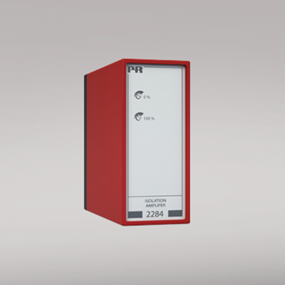
2284
Isolation amplifier
- Galvanically separated input, output, and supply
- Bipolar current / voltage input
- Signal conversion
- Current and voltage output
- 24 VDC supply or universally supplied
- Applicable in PELV/SELV circuits
Manuals : 
Data sheet :
Advanced features
- Programmable input and output ranges using internal DIP-switches.
- Front panel fine adjustment of 0 and 100% values for special ranges.
Application
- Galvanic separation of analog signals.
- Measurement of floating signals.
Technical characteristics
- Analog signal conditioning with microprocessor based gain and zero offset with a fast response time of less than 25 ms.
- Signal conversion within the ranges: -250...+250 VDC or -50...+50 mA on the input and 0...10 (20) VDC and 0...20 mA on the output.
- Galvanically separated between input, supply, and output.
- 2-wire transmitter supply and a reference voltage of 2.5 VDC, max. 15 mA for short circuit-protected supply of potentiometers.
- Buffered voltage output 0...20 V, 10 mA.
- The output can be ordered for standard 0/4...20 mA, and 0/1...5mA or special currents and selectable voltages within the signal range 0...1 VDC or and ranges 0...10 VDC.
- Output signal reversal.
- Mounting for a standard 11-pole socket which can be adapted for DIN rail or plate use with PR’s 7023 adaptor and 7024 mounting keying.
Environmental Conditions
Specifications range -20°C to +60°C Calibration temperature 20...28°C Relative humidity < 95% RH (non-cond.) Protection degree IP50 Mechanical specifications
Dimensions (HxWxD) 80.5 x 35.5 x 84.5 mm (D is without pins) Weight DC / universally supplied 125 g / 165 g Common specifications
Supply voltage 19.2...31.2 VDC Supply voltage, universal 21.6...253 VAC, 50...60 Hz or 19.2...300 VDC Max. power consumption ≤ 2.4 W (2284--D) ≤ 2.5 W (2284--P) Isolation voltage, test / working 3.75 kVAC / 250 VAC Signal / noise ratio Min. 60 dB Response time (0...90%) < 25 ms Effect of supply voltage change < 0.005% of span / VDC 2-wire transmitter supply (pin 7...5) 19...28 VDC / 20...0 mA Auxiliary voltages: Reference voltage 2.5 VDC ±0.5% / 15 mA Temperature coefficient < ±0.01% of span / °C Linearity error < 0.1% of span EMC immunity influence < ±0.5% of span Input specifications
Max. offset 50% of max. value Current input: Measurement range -50...+50 mADC Min. measurement range (span), current input 0.53 mADC Input resistance, current input Nom. 50 Ω Voltage input: Measurement range -250...+250 VDC Min. measurement range (span), voltage input 27 mVDC Input resistance, voltage input >1 MΩ...<10 MΩ Output specifications
Max. offset 20% of max. value Current output: Signal range 0...20 mA Min. signal range 4 mA Load (max.) 20 mA/1000 Ω/20 VDC Load stability, current output ≤0.01% of span / 100 Ω Current limit 23...28 mA Voltage output through internal shunt See manual for details Approvals
EMC EN 61326-1 LVD 2006/95/EC EN 61010-1 PELV/SELV IEC 364-4-41 and EN 60742 EAC TR-CU 020/2011 EN 61326-1