3114
Isolated universal converter
- Input for RTD, TC, Ohm, potentiometer, mA and V
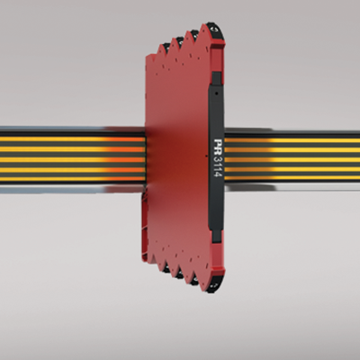
- Slimline housing of 6 mm
- 2-wire supply >15 V
- Output for current and voltage
- Can be supplied separately or installed on power rail, PR 9400
Manuals : 
Data sheet :
Application
- Linearized, electronic temperature measurement with RTD or TC sensor.
- Conversion of linear resistance variation to a standard analog current / voltage signal, i.e. from solenoids and butterfly valves or linear movements with attached potentiometer.
- Power supply and signal isolator for 2-wire transmitters.
- Process control with standard analog output.
- Galvanic separation of analog signals and measurement of floating signals.
- The device can be mounted in Safe area or in Zone 2 and Cl. 1 Div 2. area.
Advanced features
- When 3114 is used in combination with the 4501 display / programming front and ConfigMate 4590, all operational parameters can be modified to suit any application. As the 3114 is designed with electronics hardware switches, it is not necessary to open the device for setting of DIP-switches.
Technical characteristics
- A green / red front LED indicates normal operation and malfunction.
- 3-port 2.5 kVAC galvanic isolation.
Environmental Conditions
Specifications range -25°C to +70°C Storage temperature -40°C to +85°C Calibration temperature 20...28°C Relative humidity < 95% RH (non-cond.) Protection degree IP20 Installation in Pollution degree 2 & measurement / overvoltage cat. II Mechanical specifications
Dimensions (HxWxD) 113 x 6.1 x 115 mm Weight approx. 70 g DIN rail type DIN EN 60715/35 mm Wire size 0.13 x 2.5 mm2 / AWG 26...12 stranded wire Screw terminal torque 0.5 Nm Vibration: 2...25 Hz ±1.6 mm Vibration: 25...100 Hz ±4 g Common specifications
Supply voltage 16.8...31.2 VDC Fuse 400 mA SB / 250 VAC Max. power consumption 1.2 W Internal consumption 0.4 W (typ.) / 0.65 W (max.) Isolation voltage, test 2.5 kVAC Isolation voltage, working 300 VAC (reinforced) / 250 VAC (Zone 2, Div. 2) Signal / noise ratio > 60 dB Response time (0...90%, 100...10%): Temperature input ≤ 1 s Response time (0...90%, 100...10%): mA / V input ≤ 400 ms Accuracy Better than 0.1% of selected range EMC immunity influence < ±0.5% of span Extended EMC immunity: NAMUR NE 21, A criterion, burst < ±1% of span Input specifications
RTD input Pt10, Pt20, Pt50, Pt100, Pt200, Pt250, Pt300, Pt400, Pt500, Pt1000, Ni50, Ni100, Ni120, Ni1000 Linear resistance
PotentiometerCable resistance per wire (max.), RTD 50 Ω Sensor current, RTD Nom. 0.2 mA Effect of sensor cable resistance (3-/4-wire), RTD < 0.002 Ω / Ω Sensor error detection, RTD Yes Short circuit detection, RTD < 15 Ω TC input: Thermocouple type B, E, J, K, L, N, R, S, T, U, W3, W5, LR CJC via internally mounted sensor ±(2.0°C + 0.4°C * Δt) Δt = Internal temperature-ambient temperature Sensor error detection, TC Yes Sensor error current: When detecting / else Nom. 2 μA / 0 μA Current input: Measurement range 0...20 mA Current input: Programmable measurement ranges 0...20 and 4...20 mA Input resistance, current input Nom. 20 Ω + PTC 50 Ω 2-wire transmitter supply > 15 V / 20 mA Voltage input: Measurement range 0...12 VDC Programmable measurement ranges, VDC 0/0.2...1, 0/1...5, 0/2...10 VDC Input resistance, voltage input Nom. 10 MΩ Output specifications
Current output: Signal range 0…20 mA (span) Programmable current ranges 0...20 / 4...20 / 20...0 and 20...4 mA Load (max.) 20 mA/600 Ω/15 VDC Load stability, current output ≤0.01% of span / 100 Ω Sensor error indication, current output 0 / 3.5 / 23 mA / none NAMUR NE 43 Upscale/Downscale 23 mA / 3.5 mA Current limit ≤ 28 mA Voltage output: signal range 0...10 VDC Programmable voltage ranges 0/0.2...1; 0/1...5 ; 0/2...10; 1...0.2/0; 5...1/0; 10...2/0 V Load (min.) > 10 kΩ *of span = of the currently selected measurement range Approvals
EMC EN 61326-1 LVD 2006/95/EC EN 61010-1 ATEX 2004/108/EC KEMA 10ATEX0147 X IECEx KEM 10.0068X FM 3041043-C DNV Marine Stand. f. Certific. No. 2.4 GL V1-7-2 UL UL 61010-1 EAC TR-CU 020/2011 EN 61326-1 EAC Ex TR-CU 012/2011 RU C-DK.GB08.V.00410 CCOE P337347/1