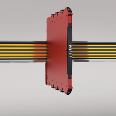
3118
Bipolar isolated converter / splitter
- Conversion of voltage and current bipolar process signals to
uni-/bipolar signals - Multiple signal ranges are selectable via DIP-switches
- Splitter function: 1 signal in and 2 signals out
- Excellent accuracy, better than 0.05 % of selected range and high output load stability
Manuals : 
Data sheet :
Application
- The 3118 is an isolating converter and splitter which can be used for signal conversion of standard bipolar analog process signals into two individual unipolar analog signals.
- The unit offers 4-port isolation and provides surge suppression and protects control systems from transients and noise.
- The 3118 also eliminates ground loops and can be used for measuring floating signals.
- Mounting of the 3118 can be in Safe area or in Zone 2 and Cl. 1 Div 2 area and is approved for marine applications.
- The analog output can be easily configured and programmed to be bipolar in the ranges ±10 mA and ±20 mA (*special setup).
Technical characteristics
- Flexible 24 VDC (±30%) supply via power rail or connectors.
- Excellent conversion accuracy, better than 0.05% of selected range.
- A green front LED indicates operation status for the device.
- All terminals are protected against overvoltage and polarity error.
- Meeting the NAMUR NE21 recommendations, the 3118 ensures top measurement performance in harsh EMC environments.
- High galvanic isolation of 2.5 kVAC.
- Fast input to output response time < 7 ms / > 100 Hz – 10 Hz bandwidth damping possible via DIP-switch.
- Excellent signal/noise ratio > 60 dB.
Mounting / installation / programming
- Easy configuration of factory calibrated measurement ranges via DIP-switches.
- A very low power consumption allows DIN rail mounting without the need for any air gap.
- Wide temperature operation range: -25...+70°C.
Environmental Conditions
Specifications range -25°C to +70°C Storage temperature -40°C to +85°C Calibration temperature 20...28°C Relative humidity < 95% RH (non-cond.) Protection degree IP20 Installation in Pollution degree 2 & measurement / overvoltage cat. II Mechanical specifications
Dimensions (HxWxD) 113 x 6.1 x 115 mm Weight approx. 70 g DIN rail type DIN EN 60715/35 mm Wire size 0.13 x 2.5 mm2 / AWG 26...12 stranded wire Screw terminal torque 0.5 Nm Common specifications
Supply voltage 16.8...31.2 VDC Max. power consumption 0.8 W Internal consumption 0.4 W (typ.) / 0.65 W (max.) Isolation voltage, test 2.5 kVAC Isolation voltage, working 300 VAC (reinforced) / 250 VAC (Zone 2, Div. 2) MTBF, acc. to IEC 61709 (SN29500) > 187 years Signal / noise ratio > 60 dB Cut-off frequency (3 dB) > 100 Hz or 10 Hz (selectable via DIP-switch) Response time (0...90%, 100...10%) < 7 ms or < 44 ms Accuracy < ±0.05% of span Temperature coefficient < ±0.01% of span / °C EMC immunity influence < ±0.5% of span Extended EMC immunity: NAMUR NE 21, A criterion, burst < ±1% of span Input specifications
Current input: Programmable measurement ranges ± 10 and ± 20 mA Functional range, current input -23...+23 mA Input voltage drop < 1 VDC @ 23 mA Voltage input: Programmable ranges ±5 and ±10 V Functional range, voltage input -11.5...+11.5 V Input resistance, voltage input ≥ 1 MΩ Output specifications
Programmable current ranges 0 / 4...20 mA Functional range, current output 0...23 mA Load (max.) 23 mA / 300 Ω / per ch. Load stability, current output ≤ 0.002% of span / 100 Ω Current limit ≤ 28 mA Programmable voltage ranges 0/1...5 and 0/2...10 V Functional range, voltage output 0...11.5 V Load (min.) > 10 kΩ Bipolar wiring and programming set-up ±10 and ± 20 mA *of span = of the presently selected range Approvals
EMC EN 61326-1 LVD 2006/95/EC EN 61010-1 ATEX 2004/108/EC KEMA 10ATEX0147 X IECEx KEM 10.0068X FM 3041043-C EAC TR-CU 020/2011 EN 61326-1 DNV Marine Stand. f. Certific. No. 2.4 GL V1-7-2 UL UL 61010-1