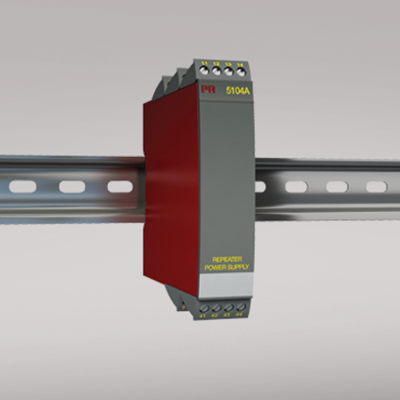
5104A
Repeater / power supply
- 1- or 2-channel version
- 3- / 5-port 3.75 kVAC galvanic isolation
- Loop supply > 17.1 V
- 20 programmable measurement ranges
- Universal supply by AC or DC
Manuals : 
Data sheet :
Application
- Power supply and signal isolator for 2-wire transmitters.
- Signal isolator for analog current / voltage signals.
- 1 : 1 or signal conversion of analog current / voltage signals.
Technical characteristics
- The 20 factory-calibrated measurement ranges in the 5104A can be selected by the internal DIP-switches without the need for recalibration. Special measurement ranges can be delivered.
- PR5104A is based on microprocessor technology for gain and offset. The analog signal is transmitted at a response time of less than 25 ms.
- Inputs, outputs, and supply are floating and galvanically separated.
- The output can be connected either as an active current / voltage transmitter or as a 2-wire transmitter.
Mounting / installation
- Mounted vertically or horizontally on a DIN rail. By way of the 2-channel version up to 84 channels per meter can be mounted.
Environmental Conditions
Specifications range -20°C to +60°C Calibration temperature 20...28°C Relative humidity < 95% RH (non-cond.) Protection degree IP20 Mechanical specifications
Dimensions (HxWxD) 109 x 23.5 x 130 mm Weight approx. 225 g DIN rail type DIN 46277 Wire size 1 x 2.5 mm2 stranded wire Screw terminal torque 0.5 Nm Common specifications
Supply voltage, universal 21.6...253 VAC, 50...60 Hz or 19.2...300 VDC Fuse 400 mA SB / 250 VAC Max. power consumption ≤ 3 W (2 channels) Internal consumption ≤ 2 W (2 channels) Isolation voltage, test / working 3.75 kVAC / 250 VAC Signal / noise ratio Min. 60 dB (0...100 kHz) Response time (0...90%, 100...10%) < 25 ms Auxiliary supply: 2-wire supply (pin 44...42 and 54...52) 28...17.1 VDC / 0...20 mA EMC immunity influence < ±0.5% of span Extended EMC immunity: NAMUR NE 21, A criterion, burst < ±1% of span Input specifications
Max. offset 20% of max. value Current input: Measurement range 0...20 mA Min. measurement range (span), current input 16 mA Input resistance, current input Nom. 10 Ω + PTC 10 Ω Voltage input: Measurement range 0...10 VDC Min. measurement range (span), voltage input 8 VDC Input resistance, voltage input > 2 MΩ Output specifications
Max. offset 20% of max. value Current output: Signal range 0...20 mA Min. signal range 16 mA Load (max.) 20 mA/600 Ω/12 VDC Load stability, current output ≤0.01% of span / 100 Ω Current limit ≤ 28 mA Max. external 2-wire supply 29 VDC Effect of external 2-wire supply voltage variation < 0.005% of span / V Voltage output: signal range 0...1 VDC / 0...10 VDC Voltage output, min. signal range 0.8 VDC / 8 VDC Load (min.) 500 kΩ *of span = of the presently selected range Approvals
EMC EN 61326-1 LVD 2006/95/EC EN 61010-1 PELV/SELV IEC 364-4-41 and EN 60742 UL UL 508 EAC TR-CU 020/2011 EN 61326-1 DNV Marine Stand. f. Certific. No. 2.4