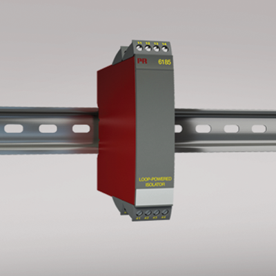
6185
Loop-powered isolator
- 1-, 2- and 4-channel galvanic isolation
- Slimline channel width of less than 6 mm
- No separate supply necessary
- Low response time
- High noise suppression
Manuals : 
Data sheet :
Application
- Galvanic separation of analog current signals.
- Elimination of ground loops and measurement of floating signals.
- A competitive choice in terms of both price and technology for galvanic isolation of current signals to SCADA systems or PLC equipment.
- Especially useful in applications necessitating an unproblematic transmission of current signals according to NAMUR (sensor error detection).
Technical characteristics
- PR 6185 is powered by the measured signal and loads the loop with max. 1.8 VDC.
- The input is protected against overvoltage and polarity error.
- The drop voltage for each channel can be calculated according to the following expression: Vdrop = 1.8 + (Iout. * Rload).
- The output is voltage-limited to 15 VDC.
- Inputs and outputs are floating and galvanically separated.
Mounting / installation
- Mounted vertically or horizontally on a DIN rail. As the devices can be mounted without distance between neighboring units, up to 168 channels can be mounted per meter.
Environmental Conditions
Specifications range -20°C to +60°C Calibration temperature 20...28°C Relative humidity < 95% RH (non-cond.) Protection degree IP20 Mechanical specifications
Dimensions (HxWxD) 109 x 23.5 x 104 mm Weight approx. 155 / 180 / 230 g (1 / 2 / 4 channels) DIN rail type DIN 46277 Wire size 1 x 2.5 mm2 stranded wire Screw terminal torque 0.5 Nm Common specifications
Internal consumption, per channel 40 mW Voltage drop < 1.8 VDC, min. 1.8 V + (Iout.*Rload), max. Isolation voltage, test 2 kVAC Signal / noise ratio Min. 60 dB (0...100 kHz) Response time (0...90%, 100...10%) < 4 ms EMC immunity influence < ±0.5% of span Input specifications
Current input: Measurement range 0...23 mA Input resistance, current input ≈ 90 Ω + Rload (@ 20 mA) Output specifications
Current output: Signal range 0...23 mA Min. signal range 1:1 Load (max.) 20 mA/600 Ω/12 VDC Load stability, current output < 0.03% of span / 100 Ω Current limit 50 mA Voltage limit 15 VDC *of span = of the presently selected range Approvals
EMC EN 61326-1 EAC TR-CU 020/2011 EN 61326-1