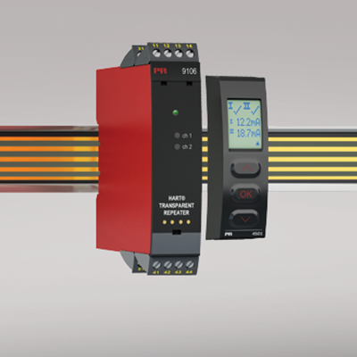
9106A
HART® transparent repeater
- 24 VDC supply via power rail or connectors
- Active and passive mA input
- Active or passive output via the same two terminals
- Splitter function - 1 in and 2 out
- SIL2 / SIL3 Full Assessment and certified acc. to IEC 61508
Manuals : 
Data sheet :
Application
- 9106A is a 1- or 2-channel isolated 1:1 repeater.
- The device supplies 2-wire SMART transmitters and can also be used for 2-wire SMART current sources. HART® & BRAIN protocols are supported and are transferred bi-directionally.
- 9106A can be mounted in and receive signals from non-classified area or zone 2.
- The PR 4511/4501 displays the process value for each channel and can be used to define high and low limits for detection of loop current level. If these limits are exceeded, the status relay will activate.
- In the 1-channel version the status relay can be used as a simple limit switch.
- Splitter application - 1 input and 2 outputs.
- In the dual channel version the 9106A can be implemented in a SIL3 loop.
Advanced features
- The detachable display and the green and red front LEDs indicate operation status for each channel.
- A tag number can be defined for each channel.
- Monitoring of error events and cable breakage on input via the individual status relay and/or a collective electronic signal via the power rail.
Technical characteristics
- High galvanic isolation of 2.6 kVAC.
- Fast response time <5 ms
- High accuracy better than 0.1%.
- 2-wire transmitter supply >16 V.
Mounting
- The devices can be mounted vertically or horizontally without distance between neighbouring units.
Environmental Conditions
Specifications range -20°C to +60°C Storage temperature -20°C to +85°C Calibration temperature 20...28°C Relative humidity < 95% RH (non-cond.) Protection degree IP20 Installation in Pollution degree 2 & measurement / overvoltage cat. II Mechanical specifications
Dimensions (HxWxD) 109 x 23.5 x 104 mm Dimensions (HxWxD) w/ 4501 / 4511 109 x 23.5 x 116 / 131 mm Weight approx. 250 g Weight incl. 4501 / 4511 (approx.) 265 g / 350 g DIN rail type DIN EN 60715/35 mm Wire size 0.13...2.08 mm2AWG 26...14 stranded wire Screw terminal torque 0.5 Nm Vibration IEC 60068-2-6 : 2007 Vibration: 2...13.2 Hz ±1 mm Vibration: 13.2...100 Hz ±0.7 g Common specifications
Supply voltage 19.2...31.2 VDC Fuse 1.25 A SB / 250 VAC Max. power consumption ≤ 3 W (2 channels) Max. internal power dissipation ≤ 2 W (2 channels) Isolation voltage, test /working: Input to any 2.6 kVAC / 300 VAC reinforced isolation Analog output to supply 2.6 kVAC / 300 VAC reinforced isolation Status relay to supply 1.5 kVAC / 150 VAC reinforced isolation SMART bi-directional communication frequency range 0.5...7.5 kHz Signal / noise ratio > 60 dB Response time (0...90%, 100...10%) < 5 ms Accuracy Better than 0.1% of selected range mA, absolute accuracy ≤ ±16 μA mA, temperature coefficient ≤ ±1.6 μA / °C Effect of supply voltage change on output (nom. 24 VDC) < ±10 μA EMC immunity influence < ±0.5% of span Extended EMC immunity: NAMUR NE 21, A criterion, burst < ±1% of span Input specifications
Current input: Measurement range 3,5...23 mA 2-wire transmitter supply 9106B1x (Uo = 28 VDC) >16 V / 20 mA 2-wire transmitter supply 9106B2x (Uo = 25.6 VDC) >15 V / 20 mA Sensor error detection: Loop break 4...20 mA < 1 mA Input voltage drop, supplied unit < 4 V @ 23 mA Input voltage drop, non-supplied unit < 6 V @ 23 mA Output specifications
Current output: Signal range 3.5...23 mA Load (max.) 20 mA/600 Ω/12 VDC Load stability, current output ≤0.01% of span / 100 Ω Current limit ≤ 28 mA Effect of external 2-wire supply voltage variation < 0.005% of span / V Max. load resistance [Ω] (Vsupply - 3.5) / 0.023 A Max. external 2-wire supply 26 VDC Status relay output terminal 33-34: Relay function N.C. Programmable low setpoint 0...29.9 mA Programmable high setpoint 0...29.9 mA Hysteresis for setpoints 0.1 mA Max. voltage, status relay 110 VDC / 125 VAC Max. current, status relay 0.3 ADC / 0.5 AAC Max. voltage - hazardous installation 32 VDC / 32 VAC Max. current - hazardous installation 1 ADC / 0.5 AAC *of span = normal measurement range 4...20 mA Approvals
EMC EN 61326-1 LVD 2006/95/EC EN 61010-1 UL UL 61010-1 DNV Marine Stand. f. Certific. No. 2.4 SIL SIL 2 certified & fully assessed acc. to IEC 61508