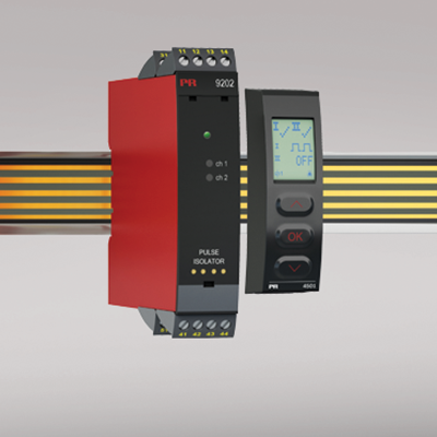
9202A
Pulse isolator
- Interface for NAMUR sensors and switches
- Extended self-diagnostics and detection of cable fault
- 1 or 2 channels
- Can be supplied separately or installed on power rail, PR type 9400
- SIL 2-certified via Full Assessment
Manuals : 
Data sheet :
Advanced features
- Configuration and monitoring by way of detachable display front (PR 4511/4501).
- Selection of direct or inverted function for each channel via PR 4511/4501.
- Advanced monitoring of internal communication and stored data.
- Optional redundant supply via power rail and/ or separate supply.
- SIL 2 functionality is optional and must be activated in a menu point.
Application
- The device can be mounted in and receive signals from non-classified area and zone 2.
- Pulse isolator for transmission of signals from NAMUR sensors and mechanical switches.
- Monitoring of error events and cable breakage via the individual status relay and/or a collective electronic signal via the power rail.
- The 9202A has been designed, developed and certified for use in SIL 2 applications according to the requirements of IEC 61508.
Technical characteristics
- 1 green and 2 yellow/red front LEDs indicate operation status and malfunction.
- 2.6 kVAC galvanic isolation between input, output and supply.
Mounting
- The devices can be mounted vertically or horizontally without distance between neighbouring units.
Environmental Conditions
Specifications range -20°C to +60°C Storage temperature -20°C to +85°C Calibration temperature 20...28°C Relative humidity < 95% RH (non-cond.) Protection degree IP20 Installation in Pollution degree 2 & measurement / overvoltage cat. II Mechanical specifications
Dimensions (HxWxD) 109 x 23.5 x 104 mm Dimensions (HxWxD) w/ 4501 / 4511 109 x 23.5 x 116 / 131 mm Weight approx. 170 g Weight incl. 4501 / 4511 (approx.) 185 g / 270 g DIN rail type DIN EN 60715/35 mm Wire size 0.13...2.08 mm2AWG 26...14 stranded wire Screw terminal torque 0.5 Nm Vibration IEC 60068-2-6 : 2007 Vibration: 2...13.2 Hz ±1 mm Vibration: 13.2...100 Hz ±0.7 g Common specifications
Supply voltage 19.2...31.2 VDC Fuse 400 mA SB / 250 VAC Max. power consumption ≤ 3 W (2 channels) Isolation voltage, test /working: Input to any 2.6 kVAC / 300 VAC reinforced isolation Analog output to supply 2.6 kVAC / 300 VAC reinforced isolation Output 1 to output 2 1.5 kVAC / 150 VAC reinforced isolation Status relay to supply 1.5 kVAC / 150 VAC reinforced isolation Communications interface Communication enabler 4511 / Programming front 4501 Response time for cable fault < 200 ms Auxiliary supplies: NAMUR supply 8 VDC / 8 mA Input specifications
Sensor types NAMUR according to EN 60947-5-6 / mechanical contact Frequency range 0...5 kHz Min. pulse length > 0.1 ms Input resistance Nom. 1 kΩ Trig level, signal < 1.2 mA, > 2.1 mA Trig level, cable fault < 0.1 mA, > 6.5 mA Output specifications
Relay output: Max. switching frequency 20 Hz Max. voltage 250 VAC / 30 VDC Max. current 2 AAC / 2 ADC Max. AC power 500 VA / 60 W Max. voltage, status relay 110 VDC / 125 VAC Max. current, status relay 0.3 ADC / 0.5 AAC Max. AC power, status relay 62.5 VA / 32 W Opto, NPN outputs: Max. switching frequency 5 kHz Min. pulse length, NPN output > 0.1 ms Max. load, current / voltage 80 mA / 30 VDC Voltage drop at 80 mA < 2.5 VDC Approvals
EMC EN 61326-1 LVD 2006/95/EC EN 61010-1 UL UL 61010-1 DNV Marine Stand. f. Certific. No. 2.4 SIL SIL 2 certified & fully assessed acc. to IEC 61508