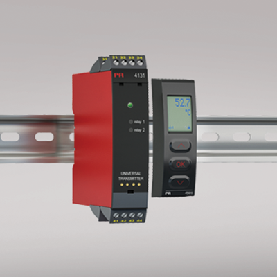
4131
Universal trip amplifier
- Input for RTD, TC, Ohm, potentiometer, mA and V
- 2 adjustable alarm limits
- FM-approved for installation in Div. 2
- 2 relay outputs
- Universal AC or DC supply
Manuals : 
Data sheet :
Advanced features
- Programmable via detachable display front (4501), process calibration, relay simulation, password protection, error diagnostics and selection of help text in several languages.
Application
- Process control with 2 pairs of potential-free relay contacts which can be configured to suit any application.
- Trip amplifier with window function defined by a high and a low setpoint. The relay changes state outside the window.
- Relay latch function, where the relay is activated and can only be reset manually.
- Sophisticated sensor error surveillance, where one relay holds the state immediately prior to the sensor error, while allowing the process to continue. The other relay can be set for sensor error alarm so that the defect sensor can be replaced immediately.
Technical characteristics
- When 4131 is used with the 4501 display / programming front, all operational parameters can be modified to suit any application. As the 4131 is designed with electronic hardware switches, it is not necessary to open the device for setting of DIP-switches.
- A green front LED indicates normal operation and malfunction. A yellow LED is ON for each active output relay.
- Continuous check of vital stored data for safety reasons.
- 3-port 2.3 kVAC galvanic isolation.
Environmental Conditions
Specifications range -20°C to +60°C Calibration temperature 20...28°C Relative humidity < 95% RH (non-cond.) Protection degree IP20 Mechanical specifications
Dimensions (HxWxD) 109 x 23.5 x 104 mm Dimensions (HxWxD) w/ 4501 / 4511 109 x 23.5 x 116 / 131 mm Weight approx. 170 g Weight incl. 4501 / 4511 (approx.) 185 g / 270 g Wire size 1 x 2.5 mm2 stranded wire Screw terminal torque 0.5 Nm Vibration: 2...13.2 Hz ±1 mm Vibration: 13.2...100 Hz ±0.7 g Common specifications
Supply voltage, universal 21.6...253 VAC, 50...60 Hz or 19.2...300 VDC Fuse 400 mA SB / 250 VAC Max. power consumption ≤ 2.0 W Isolation voltage, test / working 2.3 kVAC / 250 VAC Communications interface Communication enabler 4511 / Programming front 4501 Signal / noise ratio Min. 60 dB (0...100 kHz) Response time (0...90%, 100...10%): Temperature input ≤ 1 s Response time (0...90%, 100...10%): mA / V input ≤ 400 ms Accuracy Better than 0.1% of selected range Auxiliary supplies: 2-wire supply (terminal 44...43) 25...16 VDC / 0...20 mA EMC immunity influence < ±0.5% of span Extended EMC immunity: NAMUR NE 21, A criterion, burst < ±1% of span Input specifications
RTD input Pt10, Pt20, Pt50, Pt100, Pt200, Pt250, Pt300, Pt400, Pt500, Pt1000 Ni50, Ni100, Ni120, Ni1000, Cu10, Cu20, Cu50, Cu100 Linear resistance
PotentiometerCable resistance per wire (max.), RTD 50 Ω Sensor current, RTD Nom. 0.2 mA Effect of sensor cable resistance (3-/4-wire), RTD < 0.002 Ω / Ω Sensor error detection, RTD Yes Short circuit detection, RTD < 15 Ω TC input: Thermocouple type B, E, J, K, L, N, R, S, T, U, W3, W5, LR Cold junction compensation (CJC) via ext. sensor in connector 5910 20...28°C ≤ ±1°C, -20...20°C / 28...70°C ≤ 2°C CJC via internally mounted sensor ±(2.0°C + 0.4°C * Δt) Δt = Internal temperature-ambient temperature Sensor error detection, TC Yes Sensor error current: When detecting / else Nom. 2 μA / 0 μA Current input: Measurement range 0...20 mA Current input: Programmable measurement ranges 0...20 and 4...20 mA Input resistance, current input Nom. 20 Ω + PTC 50 Ω Voltage input: Measurement range 0...12 VDC Programmable measurement ranges, VDC 0/0.2...1, 0/1...5, 0/2...10 VDC Input resistance, voltage input Nom. 10 MΩ Output specifications
Relay output: Relay functions Setpoint, Window, Sensor error, Latch, Power and Off Hysteresis 0...100% ON and OFF delay 0...3600 s Max. voltage 250 VRMS Max. current 2 AAC or 1 ADC Max. AC power 500 VA Sensor error reaction Break / Make / Hold *of span = of the currently selected measurement range Approvals
EMC EN 61326-1 LVD 2006/95/EC EN 61010-1 FM 3025177 UL UL 508 EAC TR-CU 020/2011 EN 61326-1 DNV Marine Stand. f. Certific. No. 2.4