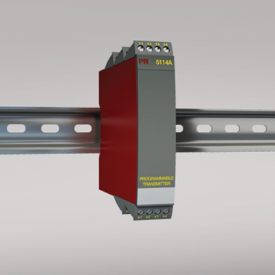
5114A
Programmable transmitter
- Input for RTD, TC, mV, linear resistance, mA, and V
- 3-port 3.75 kVAC galvanic isolation
- Current and voltage output
- Universal voltage supply
- 1- and 2-channel versions
- Loop supply > 17.1 V
Manuals : 
Data sheet :
Advanced features
- The 5114 transmitter can be configured, with or without a power supply, using the PReset software and the Loop Link communications unit.
Application
- Jumper selectable inputs for current/voltage or temperature.
- Programmable current (0...100 mA) and voltage (0...250 VDC) inputs.
- Linearized, electronic temperature measurement.
- Conversion of linear resistance variation e.g, from solenoids and butterfly valves or linear movements with attached potentiometer.
- 17.1 VDC loop and 2.5 VDC potentiometer supplies.
- Automatic 4- / 3-wire or programmable 2-wire cable compensation.
- Configurable sensor error detection including NAMUR NE43.
Technical characteristics
- Active or Passive current output and selectable voltage output.
- Separation of circuits in PELV/SELV installations.
Environmental Conditions
Specifications range -20°C to +60°C Calibration temperature 20...28°C Relative humidity < 95% RH (non-cond.) Protection degree IP20 Mechanical specifications
Dimensions (HxWxD) 109 x 23.5 x 130 mm Weight approx. 225 g DIN rail type DIN 46277 Wire size 1 x 2.5 mm2 stranded wire Screw terminal torque 0.5 Nm Common specifications
Supply voltage, universal 21.6...253 VAC, 50...60 Hz or 19.2...300 VDC Fuse 400 mA SB / 250 VAC Max. power consumption ≤ 3 W (2 channels) Internal consumption ≤ 2 W (2 channels) Isolation voltage, test / working 3.75 kVAC / 250 VAC Communications interface Loop Link Signal / noise ratio Min. 60 dB (0...100 kHz) Response time (0...90%, 100...10%): Temperature input (programmable) 400 ms...60 s mA / V input (programmable) 250 ms...60 s Updating time 115 ms (temperature input) 75 ms (mA / V / mV input) Signal dynamics, input 22 bit Signal dynamics, output 16 bit Auxiliary voltages: Reference voltage 2.5 VDC ±0.5% / 15 mA Auxiliary supply: 2-wire supply (pin 44...42 and 54...52) 28...17.1 VDC / 0...20 mA EMC immunity influence < ±0.5% of span Extended EMC immunity: NAMUR NE 21, A criterion, burst < ±1% of span Input specifications
Max. offset 50% of selected max. value RTD input Pt100, Ni100, lin. R Cable resistance per wire (max.), RTD 10 Ω Sensor current, RTD Nom. 0.2 mA Effect of sensor cable resistance (3-/4-wire), RTD < 0.002 Ω / Ω Sensor error detection, RTD Yes TC input: Thermocouple type B, E, J, K, L, N, R, S, T, U, W3, W5, LR Cold junction compensation (CJC) < ±1.0°C Sensor error current, TC Nom. 30 μA Sensor error detection, TC Yes Current input: Measurement range 0...100 mA Min. measurement range (span), current input 4 mA Input resistance: Supplied unit Nom. 10 Ω + PTC 10 Ω Input resistance: Non-supplied unit RSHUNT = ∞, VDROP < 6 V Voltage input: Measurement range 0...250 VDC -150...+150 mV Min. measurement range (span), voltage input 5 mV Input resistance, voltage input Nom. 10 MΩ (≤ 2.5 VDC) Nom. 5 MΩ (> 2.5 VDC)
Nom. 10 MΩ (mV input)Output specifications
Max. offset 50% of selected max. value Current output: Signal range 0...20 mA Min. signal range 10 mA Load (max.) 20 mA/600 Ω/12 VDC Load stability, current output ≤0.01% of span / 100 Ω Current limit ≤ 28 mA 2-wire 4...20 mA output: Signal range 4...20 mA Load stability, 4…20 mA output ≤ 0.01% of span / 100 Ω Max. load resistance [Ω] (Vsupply - 3.5) / 0.023 A Max. external 2-wire supply 29 VDC Effect of external 2-wire supply voltage variation < 0.005% of span / V Voltage output: signal range 0...10 VDC Voltage output, min. signal range 500 mV Load (min.) 500 kΩ Sensor error indication, current output Programmable 0...23 mA NAMUR NE 43 Upscale/Downscale 23 mA / 3.5 mA *of span = of the presently selected range Approvals
EMC EN 61326-1 LVD 2006/95/EC EN 61010-1 PELV/SELV IEC 364-4-41 and EN 60742 EAC TR-CU 020/2011 EN 61326-1 DNV Marine Stand. f. Certific. No. 2.4