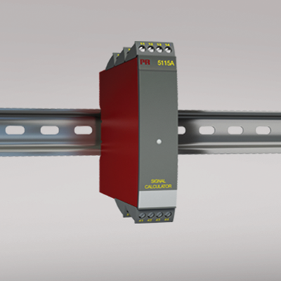
5115A
Signal calculator
- Redundancy measurement with 2 input signals
- Signal calculator with the four arithmetical operations
- Duplication of the input signal
- Input for RTD, Ohm, TC, mV, mA, and V
- Universal supply by AC or DC
Manuals : 
Data sheet :
Application
- Redundancy measurement of temperature by means of two sensors, where the secondary sensor takes over the measurement when a sensor error occurs on the primary sensor.
- Duplication of the input signal, e.g. from a temperature sensor or an analog process signal to two separate analog outputs.
- Signal calculator with four arithmetical operations: Addition, subtraction, multiplication and division.
- Example: Differential measurement:
(Input 1 * K1) - (Input 2 * K2) + K4 - Example: Average measurement:
(Input 1 * 0.5) + (Input 2 * 0.5) + K4 - Example: Different functions on the outputs:
Output 1 = input 1 - input 2, and Output 2 = input 1 + input 2 - Power supply for 2-wire transmitters.
Technical characteristics
- Within a few seconds the user can program PR5115A to a selected application using the configuration program PReset.
- A green front LED indicates normal operation, sensor error on each sensor, and functional error.
- Continuous check of vital stored data for safety reasons.
- 5-port 3.75 kVAC galvanic isolation.
Mounting / installation
- Mounted vertically or horizontally on a DIN rail. As the devices can be mounted without any distance between neighboring units, up to 42 devices can be mounted per meter.
Environmental Conditions
Specifications range -20°C to +60°C Calibration temperature 20...28°C Relative humidity < 95% RH (non-cond.) Protection degree IP20 Mechanical specifications
Dimensions (HxWxD) 109 x 23.5 x 130 mm Weight approx. 225 g Wire size 1 x 2.5 mm2 stranded wire Screw terminal torque 0.5 Nm Common specifications
Supply voltage, universal 21.6...253 VAC, 50...60 Hz or 19.2...300 VDC Fuse 400 mA SB / 250 VAC Max. power consumption ≤ 3 W Isolation voltage, test / working 3.75 kVAC / 250 VAC Communications interface Loop Link Signal / noise ratio Min. 60 dB (0...100 kHz) Response time (0...90%, 100...10%): Temperature input (programmable) 400 ms...60 s mA / V input (programmable) 250 ms...60 s Redundancy switch-over time ≤ 400 ms Signal dynamics, input 22 bit Signal dynamics, output 16 bit Auxiliary voltages: Reference voltage 2.5 VDC ±0.5% / 15 mA EMC immunity influence < ±0.5% of span Extended EMC immunity: NAMUR NE 21, A criterion, burst < ±1% of span Input specifications
Max. offset 50% of selected max. value RTD input Pt100, Ni100, lin. R Cable resistance per wire (max.), RTD 10 Ω Sensor current, RTD Nom. 0.2 mA Effect of sensor cable resistance (3-/4-wire), RTD < 0.002 Ω / Ω Sensor error detection, RTD Yes TC input: Thermocouple type B, E, J, K, L, N, R, S, T, U, W3, W5, LR Cold junction compensation (CJC) < ±1.0°C Sensor error current, TC Nom. 30 μA Current input: Measurement range 0...100 mA Min. measurement range (span), current input 4 mA Input resistance: Supplied unit Nom. 10 Ω + PTC 10 Ω Input resistance: Non-supplied unit RSHUNT = ∞, VDROP < 6 V Voltage input: Measurement range 0...250 VDC mV input: Measurement range -150...+150 mV Min. measurement range (span), voltage input 5 mV Input resistance, voltage input Nom. 10 MΩ (≤ 2.5 VDC) Nom. 5 MΩ (> 2.5 VDC) Output specifications
Max. offset 50% of selected max. value Current output: Signal range 0...20 mA Min. signal range 10 mA Load (max.) 20 mA/600 Ω/12 VDC Load stability, current output ≤0.01% of span / 100 Ω Current limit ≤ 28 mA Voltage output: signal range 0...10 VDC Voltage output, min. signal range 500 mV Load (min.) 500 kΩ 2-wire 4...20 mA output: Signal range 4...20 mA Load stability, 4…20 mA output ≤ 0.01% of span / 100 Ω Effect of external 2-wire supply voltage variation < 0.005% of span / V Max. external 2-wire supply 29 VDC Sensor error indication, current output Programmable 0...23 mA NAMUR NE 43 Upscale/Downscale 23 mA / 3.5 mA *of span = of the presently selected range Approvals
EMC EN 61326-1 LVD 2006/95/EC EN 61010-1 PELV/SELV IEC 364-4-41 and EN 60742 DNV Marine Stand. f. Certific. No. 2.4 EAC TR-CU 020/2011 EN 61326-1