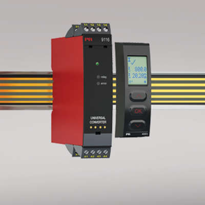
9116A
Universal converter
- Input for RTD, TC, Ohm, potentiometer, mA and V
- Supply for 2-wire transmitters
- Active / passive mA output and relay output
- Can be supplied separately or installed on power rail, PR type 9400
- SIL 2-certified via Full Assessment
Manuals : 
Data sheet :
Advanced features
- Configuration and monitoring by way of detachable display front (PR 4511/4501); process calibration, signal and relay simulation.
- Advanced relay configuration, e.g. setpoint, window, delay, sensor error indication and power monitoring.
- Copying of the configuration from one device to others of the same type via the display front.
- TC inputs with internal CJC or external CJC for higher accuracy.
- The device automatically detects whether it must supply an active or a passive current signal.
Application
- The device can be mounted in and receive signals from non-classified area and zone 2.
- Conversion and scaling of temperature, voltage, potentiometer and linear resistance signals.
- Power supply and signal isolator for 2-wire transmitters.
- Monitoring of error events and cable breakage via the individual status relay and/or a collective electronic signal via the power rail.
- 9116A has been designed, developed and certified for use in SIL 2 applications according to the requirements of IEC 61508.
Technical characteristics
- 1 green and 1 red front LED indicate operation status and malfunction. 1 yellow LED indicates relay status.
- 2.6 kVAC galvanic isolation between input, output and supply.
Mounting
- The devices can be mounted vertically or horizontally without distance between neighbouring units.
Environmental Conditions
Specifications range -20°C to +60°C Storage temperature -20°C to +85°C Calibration temperature 20...28°C Relative humidity < 95% RH (non-cond.) Protection degree IP20 Installation in Pollution degree 2 & measurement / overvoltage cat. II Mechanical specifications
Dimensions (HxWxD) 109 x 23.5 x 104 mm Dimensions (HxWxD) w/ 4501 / 4511 109 x 23.5 x 116 / 131 mm Weight approx. 185 g Weight incl. 4501 / 4511 (approx.) 200 g / 285 g DIN rail type DIN EN 60715/35 mm Wire size 0.13...2.08 mm2AWG 26...14 stranded wire Screw terminal torque 0.5 Nm Vibration IEC 60068-2-6 : 2007 Vibration: 2...13.2 Hz ±1 mm Vibration: 13.2...100 Hz ±0.7 g Common specifications
Supply voltage 19.2...31.2 VDC Fuse 1.25 A SB / 250 VAC Max. power consumption ≤ 3.5 W Isolation voltage, test /working: Input to any 2.6 kVAC / 300 VAC reinforced isolation Analog output to supply 2.6 kVAC / 300 VAC reinforced isolation Status relay to supply 1.5 kVAC / 150 VAC reinforced isolation Communications interface Communication enabler 4511 / Programming front 4501 Signal / noise ratio Min. 60 dB (0...100 kHz) Response time (0...90%, 100...10%): Temperature input (programmable) 1...60 s mA / V input (programmable) 0.4...60 s Accuracy Better than 0.1% of selected range Auxiliary supplies for 9116B1: 2-wire supply (terminal 54...52) 28...16.5 VDC / 0...20 mA Auxiliary supplies for 9116B2: 2-wire supply (terminal 54...52) 22...16.5 VDC / 0...20 mA Input specifications
RTD input Pt10, Pt20, Pt50, Pt100, Pt200, Pt250, Pt300, Pt400, Pt500, Pt1000, Ni50, Ni100, Ni120, Ni1000 Cable resistance per wire (max.), RTD 50 Ω Sensor current, RTD Nom. 0.2 mA Effect of sensor cable resistance (3-/4-wire), RTD < 0.002 Ω / Ω Sensor error detection, RTD Programmable ON / OFF Short circuit detection, RTD Yes TC input: Thermocouple type B, E, J, K, L, N, R, S, T, U, W3, W5, LR Cold junction compensation (CJC) via ext. sensor in connector 5910 20...28°C ≤ ±1°C, -20...20°C / 28...70°C ≤ 2°C CJC via internally mounted sensor ±(2.0°C + 0.4°C * Δt) Δt = Internal temperature-ambient temperature Sensor error detection, TC Programmable ON or OFF (only wire breakage) Current input: Measurement range 0...20 mA Current input: Programmable measurement ranges 0...20 and 4...20 mA Input resistance, current input Nom. 20 Ω + PTC 50 Ω Sensor error detection, current input Loop break 4...20 mA Voltage input: Measurement range 0...10 VDC Programmable measurement ranges, VDC 0/0.2...1, 0/1...5, 0/2...10 VDC Input resistance, voltage input Nom. >10 MΩ Output specifications
Current output: Signal range 0...20 mA Programmable current ranges 0...20 / 4...20 / 20...0 and 20...4 mA Load (max.) 20 mA/600 Ω/12 VDC Load stability, current output ≤0.01% of span / 100 Ω Sensor error indication, current output 0 / 3.5 / 23 mA / none NAMUR NE 43 Upscale/Downscale 23 mA / 3.5 mA Output limitation, on 4...20 and 20...4 mA signals 3.8...20.5 mA Output limitation, on 0...20 and 20...0 mA signals 0...20.5 mA Current limit ≤ 28 mA 2-wire 4…20 mA output: External 2-wire supply range 3.5...26 VDC Signal range 4…20 mA Max. load resistance [Ω] (Vsupply - 3.5) / 0.023 A Load stability, 4…20 mA output ≤ 0.01% of span / 100 Ω Effect of external 2-wire supply voltage variation < 0.005% of span / V Relay output: Relay functions Setpoint, Window, Sensor error, Power and Off Hysteresis, in % of span/display range 0.1...25 / 1...25 ON and OFF delay 0...3600 s Sensor error reaction Break / Make / Hold Max. voltage 250 VAC / 30 VDC Max. current 2 AAC / 2 ADC Max. AC power 500 VA / 60 W Max. voltage, status relay 110 VDC / 125 VAC Max. current, status relay 0.3 ADC / 0.5 AAC Max. AC power, status relay 62.5 VA / 32 W *of span = of the currently selected measurement range Approvals
EMC EN 61326-1 LVD 2006/95/EC EN 61010-1 UL UL 61010-1 DNV Marine Stand. f. Certific. No. 2.4 SIL SIL 2 certified & fully assessed acc. to IEC 61508