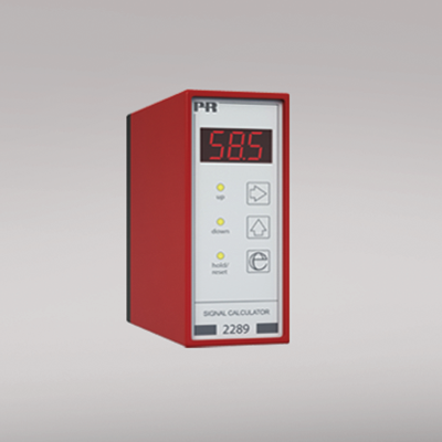
2289
Signal calculator
- Two analog inputs
- Multiple functions
- Front-programmable
- 3-digit LED display
- Version with a Pt100 input
- Analog output
Manuals : 
Data sheet :
Advanced features
- Programmed via the user interface which consists of a 3-digit display and 3 function keys in the front panel.
Application
- Operates as a PID controller with an analog or a Pt100 input.
- Functions include a manual / automatic controller, an analog calculator with a scale function on both inputs, a samplehold transmitter, a peak-hold transmitter, a delay transmitter, a signal limiter, averaging of noisy signals, monitoring of a signal’s slope, or an analog multiplexer.
Technical characteristics
- The A and B inputs can be programmed to receive current signals in the range 0...20 mA (eg. 4...20 mA), or voltage signals in the range 0...10 VDC.
- Input A is a linearized Pt100 with a 3-wire connection. input B is an analog current / voltage input.
- Digital inputs are jumper selectable NPN or PNP.
- Analog standard current / voltage output of 0/4...20 mA / 0/2...10 VDC.
- Both the input signals and the output signal can be inverted.
- Mounting for a standard 11-pole socket which can be adapted for DIN rail or plate use with PR’s 7023 adaptor and 7024 mounting keying. In environments with strong vibrations the PR 7002 can be mounted as an additional safety catch for system 2200 devices on the relay socket.
Environmental Conditions
Specifications range -20°C to +60°C Calibration temperature 20...28°C Relative humidity < 95% RH (non-cond.) Protection degree IP50 Mechanical specifications
Dimensions (HxWxD) 80.5 x 35.5 x 84.5 mm (D is without pins) Weight approx. 130 g Common specifications
Supply voltage 19.2...28.8 VDC Max. power consumption 2.7 W Internal consumption 2.4 W Signal / noise ratio Min. 60 dB Response time < 60 ms Updating time 20 ms Signal dynamics, input 20 bit Signal dynamics, output 16 bit Proportional band (XP) 0.01...999% Gain, 1/XP = 0.1...10000 Integrating time (TI) 0...999 s Differentiating time (TD) 0...999 s Effect of supply voltage change < ±0.002% of span / %V Auxiliary voltages: Reference voltage 2.5 VDC ±0.5% / 15 mA Temperature coefficient < ±0.01% of span / °C Linearity error < 0.1% of span EMC immunity influence < ±0.5% Input specifications
Max. offset 50% of selected max. value Current input: Measurement range 0...20 mA Min. measurement range (span), current input 4 mA Input resistance, current input Nom. 50 Ω Voltage input: Measurement range 0...10 VDC Min. measurement range (span), voltage input 200 mV Input resistance, voltage input Nom. 10 MΩ NPN, digital input Pull up 24 VDC / 6.9 mA PNP, digital input Pull down 0 VDC / 6.9 mA Pulse length > 50 ms RTD input Pt100 (2289B) Cable resistance per wire (max.), RTD 25 Ω Sensor current, RTD Nom. 1.25 mA Output specifications
Max. offset 50% of selected max. value Current output: Signal range 0...20 mA Min. signal range 5 mA Load (max.) 20 mA/600 Ω/12 VDC Load stability, current output ≤0.01% of span / 100 Ω Current limit 20.5 mA Voltage output through internal shunt See manual for details *of span = of the presently selected range Approvals
EMC EN 61326-1 EAC TR-CU 020/2011 EN 61326-1