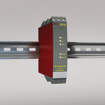
5223A
Programmable f/I-f/f converter
- Pulse calculator
- Frequency generator
- Galvanic isolation
- Analog current and voltage output
- PNP / NPN output, optional relays
- Universal supply
Manuals : 
Data sheet :
Advanced features
- The 5223 transmitter can be configured with a standard PC and the Loop Link communications unit, or delivered fully configured.
Application
- The f/I function performs frequency to current and voltage conversion.
- The f/f function can be used for pulse division or multiplication and as a buffer collecting fast pulse trains.
- A scale factor may be entered in all functions. Using both digital inputs, pulse addition or subtraction are possible.
- The frequency generator function is used as e.g. a time base or clock generator.
- Input and supply polarity reversal protection.
- Current and voltage output signals galvanically separated from the supply and the inputs.
- Programmable digital outputs including NPN, PNP or relay options.
Technical characteristics
- 5 front LEDs, indicating f1 and f2 active inputs (not NPN), Dig.out.1 and 2 active outputs, and a programmable error signal.
- Analog current output can be configured to any current within 0...20 mA range.
- Voltage output range is selectable between 0...10 VDC and 0...1 VDC by use of internal jumpers.
- Programming can be performed with or without a power supply.
Environmental Conditions
Specifications range -20°C to +60°C Calibration temperature 20...28°C Relative humidity < 95% RH (non-cond.) Protection degree IP20 Mechanical specifications
Dimensions (HxWxD) 109 x 23.5 x 130 mm Weight approx. 240 g DIN rail type DIN 46277 Wire size 1 x 2.5 mm2 stranded wire Screw terminal torque 0.5 Nm Common specifications
Supply voltage, universal 21.6...253 VAC, 50...60 Hz or 19.2...300 VDC Fuse 400 mA SB / 250 VAC Max. power consumption 3.5 W Internal consumption 3 W Isolation voltage, test / working 3.75 kVAC / 250 VAC Power-up delay 0...999 s Warm-up time 1 min. Communications interface Loop Link Signal / noise ratio Min. 60 dB Response time, analog < 60 ms + period Response time, digital output < 50 ms + period Signal dynamics, output 16 bit Effect of supply voltage change < 0.005% of span / VDC Auxiliary voltage: NAMUR supply 8.3 VDC ±0.5 VDC / 8 mA S0 supply 17 VDC / 20 mA NPN / PNP supply 17 VDC / 20 mA Special supply (programmable) 5...17 VDC / 20 mA Temperature coefficient < ±0.01% of span / °C Linearity error < 0.1% of span EMC immunity influence < ±0.5% Input specifications
Max. offset 90% of selected max. frequency Measurement range 0...20 kHz Min. measurement range 0.001 Hz Max. frequency, with input filter ON 50 Hz Min. period time with input filter ON 20 ms Input types NAMUR acc. to DIN 19234 Tacho
NPN / PNP
2-phase encoder
TTL
S0 acc. to DIN 43864Output specifications
Max. offset 50% of selected max. value Current output: Signal range 0...20 mA Min. signal range 5 mA Updating time 20 ms Load (max.) 20 mA/600 Ω/12 VDC Load stability, current output ≤0.01% of span / 100 Ω Current limit < 23 mA Voltage output through internal shunt See manual for details Voltage output: signal range 0...10 VDC Voltage output, min. signal range 250 mV Load (min.) 500 kΩ Other output types Active outputs (NPN / PNP) f/f converter output
Frequency generatorRelay output: Max. switching frequency 20 Hz Max. voltage 250 VRMS Max. current 2 AAC Max. AC power 100 VA Max. load at 24 VDC 1 A *of span = of the presently selected range Approvals
EMC EN 61326-1 LVD 2006/95/EC EN 61010-1 PELV/SELV IEC 364-4-41 and EN 60742 ATEX 2004/108/EC KEMA 04ATEX1001 EAC TR-CU 020/2011 EN 61326-1 EAC Ex TR-CU 012/2011 RU C-DK.GB08.V.00410