5343A
2-wire level transmitter
- Potentiometer or Ohmic input
- Programmable sensor error value
- High measurement accuracy
- Unique process calibration function
- Programmable via standard PC
Manuals : 
Data sheet :
Application
- Conversion of resistance variation to standard analog current signals, e.g. from Ohmic level sensors or valve positions.
- User-defined linearization function can be activated.
Technical characteristics
- Within a few seconds the user can program PR5343A to measure within the defined Ohmic values.
- Continuous check of vital stored data for safety reasons.
- The transmitter is protected against polarity reversal.
- PR5343A is configured to the current task by way of a PC, the PReset software and the communications interface Loop Link.
- The PRelevel configuration tool included in the PReset software has been developed specifically for the configuration of level applications. Among other things, it contains a function for ”on line” measurement of input span as well as a linearization function for volume linear output from horizontal cylindrical tanks.
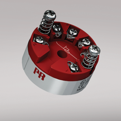
Mounting / installation
- For DIN form B sensor head or DIN rail mounting with a special fitting.
Environmental Conditions
Specifications range -40°C to +85°C Calibration temperature 20...28°C Relative humidity < 95% RH (non-cond.) Protection degree (encl./terminal) IP68 / IP00 Mechanical specifications
Dimensions Ø 44 x 20.2 mm Weight approx. 50 g Wire size 1 x 1.5 mm2 stranded wire Screw terminal torque 0.4 Nm Vibration IEC 60068-2-6 : 2007 Vibration: 2...25 Hz ±1.6 mm Vibration: 25...100 Hz ±4 g Common specifications
Supply voltage 8.0...35 VDC Internal consumption 25 mW…0.8 W Voltage drop 8.0 VDC Warm-up time 5 min. Communications interface Loop Link Signal / noise ratio Min. 60 dB Accuracy Better than 0.1% of selected range Response time (programmable) 0.33...60 s Signal dynamics, input 19 bit Signal dynamics, output 16 bit Effect of supply voltage change < 0.005% of span / VDC EMC immunity influence < ±0.5% of span Input specifications
Max. offset 50% of selected max. value Linear resistance input: Measurement range / min. range (span) 0...100 kΩ / 1 kΩ Min. measurement range 1 kΩ Cable resistance per wire (max.), lin. R 100 Ω Sensor current, lin. R > 25 μA, < 120 μA Effect of sensor cable resistance (3-wire), lin R. < 0.002 Ω / Ω Sensor error detection, lin. R Yes Output specifications
Current output: Signal range 4…20 mA Min. signal range 16 mA Updating time 135 ms Load resistance, current output ≤ (Vsupply - 8) / 0.023 [Ω] Load stability, current output ≤0.01% of span / 100 Ω Sensor error indication, current output Programmable 3.5…23 mA NAMUR NE 43 Upscale/Downscale 23 mA / 3.5 mA *of span = of the presently selected range Approvals
EMC EN 61326-1 ATEX 2004/108/EC KEMA 10ATEX0004 X IECEx DEK 13.0036X INMETRO DEKRA 13.0002 X EAC TR-CU 020/2011 EN 61326-1 DNV Marine Stand. f. Certific. No. 2.4 GL V1-7-2