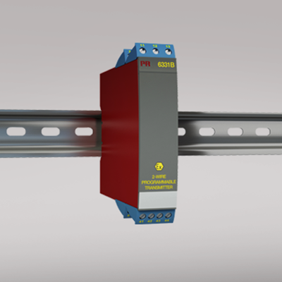
6331B
2-wire programmable transmitter
- RTD, TC, Ohm, or mV input
- Extremely high measurement accuracy
- Galvanic isolation
- Can be installed in Ex zone 0
- 1- or 2-channel version
Manuals : 
Data sheet :
Application
- Linearized temperature measurement with Pt100...Pt1000, Ni100...Ni1000, or TC sensor.
- Conversion of linear resistance variation to a standard analog current signal, for instance from valves or Ohmic level sensors.
- Amplification of a bipolar mV signal to a standard 4...20 mA current signal.
Technical characteristics
- Within a few seconds the user can program PR6331B to measure temperatures within all ranges defined by the norms.
- The RTD and resistance inputs have cable compensation for 2-, 3- and 4-wire connection.
- A limit can be programmed on the output signal.
- Continuous check of vital stored data for safety reasons.
Mounting / installation
- Mounted vertically or horizontally on a DIN rail. Using the 2-channel version, up to 84 channels can be mounted per meter.
- NB: As Ex barrier we recommend 5104B, 5114B, or 5116B.
Environmental Conditions
Specifications range -40°C to +60°C Calibration temperature 20...28°C Relative humidity < 95% RH (non-cond.) Protection degree IP20 Mechanical specifications
Dimensions (HxWxD) 109 x 23.5 x 104 mm Weight (1 / 2 channels) 145 / 185 g Wire size 1 x 1.5 mm2 stranded wire Common specifications
Supply voltage 7.2...30 VDC Internal consumption, per channel 0.17...0.8 W Voltage drop 7.2 VDC Isolation voltage, test / working 1.5 kVAC / 50 VAC Isolation voltage, ch. 1 / ch. 2 1500 VAC Warm-up time 5 min. Communications interface Loop Link Signal / noise ratio Min. 60 dB Accuracy Better than 0.05% of selected range Response time (programmable) 1...60 s EEprom error check < 3.5 s Signal dynamics, input 20 bit Signal dynamics, output 16 bit Effect of supply voltage change < 0.005% of span / VDC EMC immunity influence < ±0.5% of span Extended EMC immunity: NAMUR NE 21, A criterion, burst < ±1% of span Input specifications
Max. offset 50% of selected max. value RTD input Pt100, Ni100, lin. R Cable resistance per wire (max.), RTD 5 Ω Sensor current, RTD Nom. 0.2 mA Effect of sensor cable resistance (3-/4-wire), RTD < 0.002 Ω / Ω Sensor error detection, RTD Yes TC input: Thermocouple type B, E, J, K, L, N, R, S, T, U, W3, W5, LR Cold junction compensation (CJC) < ±1.0°C Sensor error detection, TC Yes Sensor error current: When detecting / else Nom. 33 μA / 0 μA Voltage input: Measurement range -12...800 mV Min. measurement range (span), voltage input 5 mV Input resistance, voltage input 10 MΩ Output specifications
Current output: Signal range 4…20 mA Min. signal range 16 mA Updating time 440 ms Load resistance, current output ≤ (Vsupply - 7.2) / 0.023 [Ω] Load stability, current output ≤0.01% of span / 100 Ω Sensor error indication, current output Programmable 3.5…23 mA NAMUR NE 43 Upscale/Downscale 23 mA / 3.5 mA *of span = of the presently selected range Approvals
EMC EN 61326-1 ATEX 2004/108/EC KEMA 06ATEX0115 EAC TR-CU 020/2011 EN 61326-1 EAC Ex TR-CU 012/2011 Yes